Automated Prescriptive Maintenance for IIoT & Industry 4.0
VibroBox is a digital signal processing (DSP) service focused on prescriptive maintenance, vibration diagnostics, and condition monitoring algorithms for a broad range of equipment. We are using cloud technologies, machine learning and neural networks, wavelet analysis, fuzzy logic and other proprietary algorithms to automatically process and analyze vibration signals and telemetry data from different types of sensors. Our team of scientists, engineers, and industry experts is lead by Igor Davydov, Ph.D. who has more than ten years’ experience in data science, digital signals processing, and vibration diagnostics.
Detailed equipment health reports and maintenance guidelines are readily available from any device in the service's dashboard. Furthermore, the maximum efficiency is achieved through a direct integration with enterprise management systems (CMMS, MES, ERP, SCADA, etc.). The obvious way to implement this integration is via global service platform-integrator solutions for the Industrial Internet of Things (IIoT) and Industry 4.0. The largest solutions on the market are General Electric and Microsoft with Predix platform for Industrial Internet, NVidia and SAP with SAP Cloud Platform for the Internet of Things and Intel with its Intel IoT Platform. Therefore, our primary goal is to become an essential diagnostics service within IIoT and Industry 4.0 concepts.
We have thoroughly tested VibroBox at industrial facilities in Belarus, including Geely automobile factory, several equipment testing laboratories, rolling mills, compressors, engines and other rotary equipment, generators and wheel pairs.
VibroBox key features:
- truly automatic diagnostics, no humans are involved;
- detailed and precise defects detection and reporting (rotor imbalance, shaft runout, wear of the outer ring of the bearing/gear, etc.);
- almost every type of equipment is supported and prior "training" step for our technology is not required;
- easy scalability;
- a wide range of industrial vibration sensors is supported;
- integration with enterprise management systems;
- continuous service improvement by our scientific team.
In comparison, competitor solutions usually fall into one of the following categories:
- Condition monitoring systems that collect the data and support generalized notifications such as "something is wrong."
- Non-automatic systems that rely upon manual diagnostics by a team of experts. Sometimes the monitoring system is used to notify human experts.
- Non-scalable automatic systems which require a long-term and expensive R&D for each specific type of equipment (proprietary software development, telemetry data collection for all possible defect combinations, attempts to train neural networks using these datasets, etc.).
We are also experimenting with algorithms for efficient features selection from acoustic, heart murmur and other non-vibration signals. These algorithms can either significantly increase the efficiency of existing AI frameworks (Google Cloud Machine Learning Services, Microsoft Azure Batch AI Training, etc.) or become a core of a new universal DSP cloud classifier service.
The structure of the service, sensors, data processing algorithms and the role of VibroBox in IIoT are described in more detail below.
Table of Contents
1. What is vibration-based diagnostics and condition monitoring?
2. The working principle of VibroBox
3. Prerequisites to the emergence of VibroBox
3.1. Condition monitoring of industrial equipment: traditional challenges
3.2. Vibration-based condition monitoring as part of the Industry 4.0 concept
3.3. What prevents contemporary vibration-based condition monitoring from becoming part of Industry 4.0?
3.4. What makes VibroBox as unique service?
5.3. Communication and telemetry data transmission unit
5.4. VibroBox ICP (IEPE) converters
5.5. Telemetry data acquisition unit mounted on a DIN rail
6. VibroBox data processing system
6.1. Vibration signal and telemetry data
6.2. Automatic analysis of kinematic scheme
6.3. Tracking the rotational speed of rotary equipment components by vibration signals
6.4. Algorithms to compute ISO, GOST, crest factor, kurtosis, and other metrics
6.5. Algorithms for vibration signal spectrum and envelope spectrum analysis
6.6. Algorithms for wavelet processing of vibration signal
6.7. Basis wavelet function adapted to isolate shock pulse processes
6.8. The vector of informative features of equipment technical condition
6.9. Classification of defects in the domain of informative features
6.10. Generation of prescriptions for asset technical management
6.11. VibroBox service operating results
6.12. Promising and experimental algorithms
7. Further development of VibroBox
1. What is vibration-based diagnostics and condition monitoring?
Defects of industrial equipment that were not detected in time will lead to the occurrence of emergency situations and will entail substantial losses of time, money, and in some cases, negative consequences for people and the environment. On the other hand, condition-based (CBM) maintenance, predictive maintenance (PdM), and primarily prescriptive maintenance (RxM) can significantly increase the lifespan of the equipment and its overall reliability, and thereby significantly reduce overall investment in the business.
Vibration-based diagnostics is the tool that allows you to detect defects in the industrial equipment related to physical wear and tear of its components and other operational factors. Application of prediction methods, based on in-depth analysis of vibration signals, allows for increasing the intervals between repairs, as well as for preventing accidents associated with unacceptable wear and tear of mechanical components of industrial equipment. This will allow for eliminating the possibility of unplanned repairs of sudden equipment failure and, in the long run, significantly reduce planned downtime in production cycles by moving to proactive, prescriptive maintenance. There is no need to store extra spare parts and materials in a warehouse or make additional planned and preventable repairs.
VibroBox solves the tasks of vibration diagnostics in a comprehensive manner and on a new level. VibroBox is a universal scalable service that allows in-depth condition monitoring and failure prediction of industrial equipment through processing and analysis of its vibration signals and telemetry data. To solve these tasks VibroBox, based on cloud technologies of data storing and computing, uses the most efficient and progressive methods of data processing, such as wavelet analysis, creating proper basis vectors, algorithms of fuzzy logic, and many more.
VibroBox service greatly reduces maintenance costs for a wide range of rotary and reciprocating equipment, including generators, engines, turbines, pumps, compressors, fans, blowers, gearboxes, bearings, rolling mills, etc. This is possible, because:
- Efficient diagnostics and detailed internal defects description prevents emergencies and unplanned machinery downtimes.
- Timely maintenance significantly increases the lifespan of the equipment and improves its overall reliability.
- Condition-based, predictive and mainly prescriptive maintenance increases the intervals between equipment servicing. Worn equipment parts are replaced only when necessary, lubricants are changed, and manufacturing methods are adjusted only as needed, rather than on a fixed schedule for planned or preventive maintenance.
- VibroBox is vertically scalable. You can start diagnosing a new equipment type as soon as it’s kinematic scheme is uploaded.
- Changes in manufacturing methods or operating modes of equipment do not require any additional tuning.
- Completely unmanned production (as declared in the Industry 4.0 concept) becomes possible. Operational control, forecasting, and decision-making are fully automated and do not require human operators or experts.
- A lot of resources previously engaged in excessive operational control and maintenance of equipment are freed up.
- Integration with enterprise management systems (CMMS, MES, ERP) automates and optimizes many business processes.
2. The working principle of VibroBox

The vibration signal and other telemetry data (acoustic signal, temperature, oil or gas pressure, etc.) are transmitted through wired or wireless communication channels, and then accumulated and analyzed by various algorithms. Finally, VibroBox reports a description of all internal defects and detailed maintenance recommendations. These reports are accessible on the user's account dashboard or directly submitted into an enterprise management system (CMMS, MES, ERP).
For more details on how VibroBox works, see section “VibroBox service concept”.
3. Prerequisites to the emergence of VibroBox
3.1. Condition monitoring of industrial equipment: traditional challenges
One of the most common problems in the industry is access to the equipment’s health data when necessary. Online condition monitoring involves continuous tracking of many operating parameters (temperature, overall vibration level, crest factor, etc.) and the system (or operator) response when these parameters exceed the allowable limits. The response may include stopping the process, detailed diagnostics of equipment problems, or repair.
Depending on the extent of expert involvement in the evaluation, we distinguish between expert-oriented and automated condition monitoring systems.
Expert-oriented condition monitoring of industrial equipment
In this way, an industrial enterprise creates a condition monitoring department with a team of experts. These experts use special tools to acquire and process telemetry data. Then they analyze the parameters of these signals (usually using spectral methods) and try to evaluate the technical condition of industrial equipment and identify the defects of its specific parts.
Automated condition monitoring systems
The future of equipment condition monitoring systems is in fully automated solutions, and manufacturers of condition monitoring systems are developing the solutions. There are some vibration-based condition monitoring systems (usually stationary), which can work in automatic mode for specific industrial equipment. The commissioning of such a system implies a long phase of research. During this phase, the same team of experts (formed with internal staff or via outsourcing) build a mathematical model, acquire informative features and create specialized software capable of monitoring the condition of the specific unit of equipment under specified operating conditions. This process is not so much a solution to the issue, but rather an attempt to train the condition monitoring equipment by projecting the limited experience of the expert team upon it, and only this experience serves as a decision-making foundation.
Finally, solving the tasks of vibration-based condition monitoring in this way is extremely expensive — both organizationally and financially. Training, personnel motivation, monitoring of their work practices and continuity of experience, procuring expensive vibrating hardware systems — all of that is only part of the problem. Such a solution to the issue does not scale well, forcing the company to repeat all previously completed stages of implementation with significant changes in production processes and to start from the very beginning every time. The organizational and support costs of vibration-based condition monitoring are becoming unreasonably high.
Taking into account all factors described above, the implementation of such ways is an extremely lengthy, time-consuming and expensive process.
Thus, it is possible to identify the main problems of traditional vibration-based condition monitoring:
- high threshold of implementation — both organizational and financial;
- costly training, motivation, control and a lack of experience of experts;
- expensive procurement and maintenance of operational condition of vibration-based condition monitoring tools;
- technical and organizational obstacles of scaling systems;
- problems of integration with enterprise management systems (CMMS, MES, ERP).
VibroBox is the condition monitoring service, which through the optimal usage of traditional algorithms of digital signal processing and machine learning solves the task of automatic condition monitoring of industrial equipment. This is achieved without creating any specialized stationary systems and without preliminary research made by the “on-site” team of experts. It actually makes VibroBox an easily scalable condition monitoring service that constantly self-trains with an array of vibration signals accumulated with a wide range of service-connected equipment every day.
3.2. Vibration-based condition monitoring as part of the Industry 4.0 concept
Industry 4.0 is a term that describes the European initiative for global implementation of cyber-physical systems [1] in production processes and enterprise management systems (CMMS, MES, ERP), which should lead the industry to the Industry 4.0. In 2014, the United States followed Germany and created a non-commercial consortium for the Industrial Internet of Things, which is led by such industry giants as General Electric, AT&T, IBM and Intel.
This concept creates an important role for condition monitoring systems. Equipment, which is operating as part of Industrial Internet of Things (IIoT) must be able to report on its self-identified issues and required technical maintenance to the enterprise management system by usage of built-in or pre-installed fully automated condition monitoring systems.
Diagnostics of equipment defects (down to specific parts) can predict the remaining life of each part, giving recommendations for its maintenance — all of this should take place without the participation of experts or operational staff (i.e. human influence on decision-making must be eliminated as much as possible).
In this way, the enterprise management system receives initial data for equipment maintenance planning directly from the condition monitoring system. The condition monitoring system reports can help by performing the following tasks:
- check for the availability of essential parts at the warehouse
- order repairs if necessary
- find a window in the technological process
- generate a request for on-the-spot and in-timely service (without prolonged stoppages, complete assembly-disassembly of the equipment for troubleshooting, etc.).
Naturally, a decision-making system capable of solving these tasks and constant self-training using continuously accumulated arrays of vibration signals can confidently function only within a cloud service. Cloud technologies will also be used for clear integration of the Condition Monitoring System with the help of the Enterprise Management System.
An efficient automatic system of in-depth condition monitoring with full integration into the enterprise management system constitutes the need within the concept of the Industrial Internet of Things, which we are already achieving within VibroBox.
Moreover, the task of objective technical condition monitoring of equipment is shifted towards equipment manufacturers and encourages them to supply their products with built-in automatic systems for online vibration-based condition monitoring. At unmanned production facilities of the future, there is no place for vibration-based condition monitoring departments.
How does business benefit from this?
- Operated equipment becomes more reliable. This helps prevent accidents and downtime, significantly increases the remaining life of the equipment, and the time between repairing and servicing, and its overall reliability.
- Production processes become less redundant. It helps to exclude unnecessary downtime of technological processes, to free high-cost specialists from inspecting equipment and to get us closer to unmanned technology in general. It releases resources that were previously used for preventive maintenance of equipment.
- Integration of technological systems with enterprise management systems and business process optimisation. Technology for automatic control of production resources has almost become a reality, and decision-making depends on reliable forecasting results. The production environment gets the opportunity to significantly reduce the risks associated with unexpected failures. In addition, we receive access to exhaustive history — from the very inception of the defect until the critical condition, which is extremely important in terms of equipment warranty support.
In-built online vibration-based condition monitoring systems allow the manufacturer to keep an eye on the operation of their equipment. In this way, the manufacturer knows exactly how and why their equipment has failed. The condition monitoring system gives timely predictive maintenance recommendations (for example, replacing dirty lubricant), which enables us to use this equipment with maximum efficiency by reducing the impact of the factors that shorten the remaining life of the equipment. When something wears out and fails, the manufacturer gets an opportunity in advance to prepare spare parts and materials, as well as plan for repairs without affecting the production process. And most importantly, the manufacturer controls the operation of the equipment during the warranty period, knows the conditions and modes of operation and can clearly distinguish a warranty case from a non-warranty one and justify it with an evidence-based database.
If the equipment manufacturer plans to maintain its market position in the future, it will find these processes inevitable.
It should be noted that currently manufacturers interpret these tasks differently. Some manufacturers are trying to incorporate the companies that specialize in vibration-based condition monitoring into their holdings, thus the issue of the condition monitoring system is resolved. Others have access to the condition monitoring service of industrial equipment through partnerships and cooperation agreement.
3.3. What prevents contemporary vibration-based condition monitoring from becoming part of Industry 4.0?
Currently, intelligent systems for technical condition monitoring of equipment, which are able to solve tasks in accordance with the requirements of the Industrial Internet of Things are being actively developed.
The technological opportunity for technical condition monitoring of complex equipment as a remote and fully automatic service appeared relatively recently thanks to the revolutionary advances in information technology. The above include cloud-based data storage and processing technologies, new ways of data processing, such as wavelet analysis, Hilbert-Huang transform, creating proper basis, machine learning, techniques to reduce the size of training data sets and fast wireless transmission channels for large arrays of digital telemetry data.
There are a number of difficulties that developers of such systems face:
- The high price of errors in the technological system;
- Generation and validation of the training set;
- Generation of the informative features domain;
- The need to develop a number of additional algorithms.
I. Price of errors in the technological system
Within the fully automatic systems of Industry 4.0, the function of an expert becomes that of an observer. Thus the demand for reliable defect identification and operational sustainability of such systems is extremely high.
Technological systems in terms of the cost of errors can be divided into three groups:
- The price of single errors is small. Good examples are any game scenarios. Here, the price of an error in the system is small. No accident will happen and no one will get hurt if an app such as Prisma or Fabby draws a picture in the wrong way. It would not be critical, if in a dark (or too bright) room, the MSQRD algorithm failed.
- The price of single errors is moderate. A classic example is a credit score system. The idea is to evaluate the overall effectiveness of the system from a good distance. Single errors are a nuisance, but they can definitely occur as part of common use (they are also included in the system as potential risks). Such scenarios require in-depth research of mathematical models, thoughtful work with training data sets, selection of the activation function, etc. Serious scientific teams and sometimes entire departments of leading universities are engaged in this.
- The price of single errors is high. In areas such as medicine, extraction and refining of hydrocarbon raw materials, transportation, condition monitoring of industrial systems, accidents and disaster prevention, the price of single errors in the decision-making system is extremely high. In these scenarios, direct use of neural networks is usually avoided, mainly because of the unobvious decision-making and difficulties with the removing of classification errors. This is why a lot of attention is paid to generation of informative features domains for machine learning, as well as to decision-making systems updating more stable and clearer algorithms, for example, based on fuzzy logic (which allows simulating the work of the expert with the system of assumptions and their verification).
II. Generation and validation of the training set
Modern methods of machine learning, especially neural networks, require large training data sets to operate.
The main progress of machine learning methods is now seen in areas such as image processing, speech technologies, text processing, medicine (medical image processing and working with medical history). These areas are similar in the way that large and properly spaced data as training sets for machine learning algorithms have either been already selected and are available, or can be prepared relatively easily (or bought). The situation is, however, rather different for those areas that lack training data sets, or where they cannot be quickly collected and generated in the required volume.
Vibration-based condition monitoring is one such problem area. There are currently no databases of validated vibration signals prepared for machine learning. The reason is that historically vibration-based condition monitoring has been an expert-dependent area, and an expert was trained first, rather than a machine; source vibration signals as training data were not collected.
The second part of the problem is associated with the unusually wide range of equipment undergoing diagnostics for different industries. That is why generation and validation of the complete training sets for universal condition monitoring systems is an extremely difficult task.
III. Generation of the informative features domain
Machine learning algorithms solve the task of classifying objects in the domain of informative features. This domain is a numeric description of classifying objects as vectors of values that correspond to a certain set of features for this object. By analysing these data, machine learning algorithms use them to self-train and then classify the objects into predefined classes.
Condition monitoring techniques that are widely used at present (metric methods, as well as the vibration signal spectrum and signal envelope spectrum) generate the domain of informative features of equipment defects in a form that is extremely inconvenient for automatic systems. The main problem is that the scope of this description is not sufficient at all for steady work of machine learning algorithms and their use as the basis for implementing universal systems for technical condition monitoring of industrial equipment. This is due to the fact that traditional methods of vibration signal processing are very simple; they were proposed more than 50 years ago and are still actively used. In addition, vibration-based condition monitoring has traditionally been an expert-oriented field of knowledge and a human as expert is not physically capable of working with the domain of informative features of large dimensions.
IV. The need to develop a number of additional algorithms
Expert-oriented systems lack a number of algorithms that are required for fully automated systems.
For example, the algorithm for tracking the rotational speed of equipment’s rotary components supports mechanisms operating in a non-stationary mode (the most vivid example is vehicles).
Automatic analysis of the kinematic scheme of the mechanism is required for a universal and scalable diagnostics service (in particular, to generate the domain of informative features of all potential defects of equipment undergoing diagnostics). This work is usually performed by vibration diagnostics experts.
These and other algorithms that have been developed by our team are the part of the intellectual property of the project.
3.4. What makes VibroBox a unique service?
VibroBox employs the latest methods of processing and analysing vibration signals and telemetry data for fully automatic condition monitoring and fail prediction of industrial equipment. We use the cloud-based data storage and processing technologies, wavelet analysis, creating proper bases, machine learning and more. As a rule, for solving these tasks in industry, specialized stationary condition monitoring systems are created, this requires large investment and time expenditures for carrying out research for equipment. At the same time, such condition monitoring systems are closed software and hardware complexes, for which the limited experience of a team of experts serves as a decision-making foundation. As a consequence, such systems are extremely difficult to measure and they are completely deprived of the opportunities for independent learning by way of analyzing the accumulated experience in the form of data on the equipment functioning and failures.
Principles of operation, architecture and applied signal processing methods makes VibroBox as easily measurable condition monitoring service. It is constantly trained on a daily collection of vibration signals from the widest range of equipment connected to the service. In this case, a detailed condition monitoring of equipment and many recommendations are available for new customers even with the first use of VibroBox, without any training. The use of forecasting methods, which are based on a large history of continuously collected data, provides an opportunity to move from preventive maintenance of equipment to condition-based (CBM) and predictive maintenance (PdM), significantly increasing the lifespan of the equipment and its overall reliability, eliminating the possibility of accidents and sudden failures and ensuring high availability.
With all these advantages, the cost of using the VibroBox service is much lower than the overall investment for the deployment of and support for highly specialized local condition monitoring systems.
The scope of VibroBox service usage is not limited by industrial equipment only. Already, the service and operation organizations of railway locomotives and trucks are getting interested in our project.
VibroBox also can work with vibroacoustic signals received in any way accessible to the user — up to using a microphone built into a smartphone, tablet or PC or transferring to VibroBox pre-recorded vibroacoustic signals. For these purposes, our team also developed applications for mobile platforms (Android, Apple), which, in addition to transferring data to VibroBox, have full functionality for giving ready-made reports. These VibroBox opportunities will be the simplest tools to express condition monitoring of your equipment.
4. VibroBox service concept
The main novelty of VibroBox is not in data transmission systems, or sensors, but in methods of vibration signal processing that allow generation of the convenient domain of informative features for classifiers (support vector machine and neural networks). It is due to this that the service becomes fully automatic, and vibration-based condition monitoring gets new opportunities for solving the tasks as part of the Industrial Internet of Things and Industry 4.0.
Algorithms for condition monitoring of equipment implemented as part of VibroBox are responsible for identifying the sets of informative features and solving classification tasks using the domain of informative features. A result of the classifier work is the formalization of the equipment condition within one of the classes, which are based on the analysis of the kinematic scheme and evaluation of a parametric model. Thus, VibroBox determines the current equipment condition, including defects of its specific parts. Based on the condition of the identified equipment, its defects and the dynamics of their development, VibroBox gives equipment condition monitoring and predictive maintenance reports.
All the algorithms, on which VibroBox is based, operate as a cloud computing. Physically, these are separate servers that process telemetry data and are measured independently of the rest of VibroBox.
Many algorithms developed by the VibroBox team did not exist before. For example, the algorithm of tracking the rotational speed of equipment rotary components by vibration signals, a set of algorithms for the analysis of the kinematic scheme of the mechanism, etc.
The scheme of the operation principle of VibroBox is presented in Figure 2.
The sources of vibration signals and telemetry data transmit initial data to VibroBox, whether it is a vibrational or acoustic signal, temperature or other necessary telemetry data.
The data processing system is responsible for the processing of data received, generating the equipment condition monitoring and predictive maintenance reports. This part of VibroBox includes both traditional and our own, newly developed, algorithms.

The data processing system solves the following tasks:
- generation of the domain of informative features, including:
- automatic analysis of equipment kinematic scheme;
- tracking the rotational speed of equipment rotary components by vibration signals;
- metrics computing;
- vibration signal spectrum and envelope spectrum analysis;
- wavelet processing of the vibration signal.
- classification of defects in the domain of informative features, consisting of the following stages:
- classification of defects;
- subsequent validation of defects.
- generation of prescriptions for asset technical management.
Classification of equipment defects, in the generated multi-dimensional domain of informative features, is carried out by algorithms working on the basis of a neural network and fuzzy logic. The classification results are the results of VibroBox as a whole, i.e. equipment condition monitoring and predictive maintenance reports.
Detailed results, status reports and recommendations are accessible through VibroBox user's personal account and can be automatically submitted through VibroBox API to enterprise management systems (CMMS, MES, ERP).
5. VibroBox hardware platform
5.1. General information
To monitor the condition of the equipment, VibroBox analyses vibration and acoustic signals, temperature, and other telemetry data. Signals are detected by specialised sensors. The characteristics completely satisfy the strictest requirements for quality and completeness of telemetry data acquisition.
VibroBox supports typical vibration sensors (in particular, PCB Piezotronics, Bernecker + Rainer (B&R) and SKF), such as accelerometers with built-in ICP (IEPE) electronics, which are widely used in industrial process control systems. This allows VibroBox to process signals from sensors already built into the equipment and makes VibroBox a universal service for condition monitoring of industrial equipment.
The figures below show an example of data acquisition sets using the VibroBox sensor (see Figure 3) and the accelerometers with built-in ICP (IEPE) electronics (see Figure 4). The description of individual devices from these sets is given below.


Moreover, VibroBox uses the vibration sensors and microphones built into mobile platforms (in particular smartphones and laptops) as initial data sources. The results obtained by our team show that in many cases, condition monitoring of equipment made by the scenario “bring the smartphone close to the equipment, record vibration and acoustic signals; transfer them to the VibroBox; receive and view the condition monitoring report on the smartphone screen” is quite informative.
Thus, VibroBox becomes a universal service for condition monitoring of equipment — without being tied to any kind of hardware measuring platform.
5.2. Telemetry sensors
DVS series of VibroBox vibration sensors are designed to be installed on the equipment undergoing diagnostics in order to acquire necessary telemetry data and transmit it to the communication and telemetry data transmission unit. They function in the mode of continuous measurement of the absolute vibration and temperature of machines and mechanisms under industrial operation conditions. Each VibroBox unit is supplied in full operational readiness and requires no any additional maintenance or customization.
There are three design versions of DVS series sensors, each of which is determined by specific application conditions. In this case, the range of existing VibroBox sensors does not cover all possible installation options and other operational and technological limitations, so the range of VibroBox sensors is expanded as necessary.
The DVS1602/2Ch and DVS1610/2Ch sensors consist of a primary acceleration transducer (dual-axis MEMS transducer), a temperature sensor and a secondary (measuring) transducer build into a common rectangular (DVS1602/2Ch) and cylindrical (DVS1610/2Ch) housings.
The DVS1703 sensor consists of two parts:
- the first part: contains a primary acceleration transducer (dual-axis MEMS transducer) and a primary temperature transducer mounted in a single cylindrical housing;
- the second part: contains a digital measuring transducer mounted in a second cylindrical body.
Both parts are connected by a cable, the length of which is determined by the specific conditions of use.
The views of the VibroBox DVS sensors is shown in Figure 5.


Figure 5 — the VibroBox DVS series vibration sensors.
The characteristics of DVS series sensors:
|
Name of the characteristic |
Value of the characteristic |
|
Type of primary transducer |
dual-axis MEMS acceleration transducer |
|
Acceleration measurement range |
|
|
Measurement range of vibration frequencies |
from 4 to 22 kHz |
|
Sensor mechanical resonance frequency |
22 kHz |
|
Built-in ADC bitness |
24 bit |
|
Built-in ADC sampling frequency |
96 kHz |
|
Operating conditions: |
|
|
climatic performance |
UHL 1 by GOST 15150-69 / CT by DS/IEC 721-2-1 |
|
range of working temperatures * |
from minus 40 to +85°C |
|
Degree of protection provided by enclosure |
IP67 (in accordance with IEC 60529-2004 / GOST 14254-96) |
|
Sensor mounting type |
mounting by steel stud with metric thread |
|
Overall dimensions: |
|
|
DVS1602/2Ch |
80 × 60 × 55 mm (Width × Depth × Height) |
|
DVS1610/2Ch |
95 × 35 mm (Depth × Diameter) |
|
DVS1703: |
|
|
part with primary sensor |
24 × 17 mm (Depth × Turnkey size) |
|
part with measuring transducer |
93 × 35 mm (Depth × Diameter) |
|
Sensor weight (without cable): |
|
|
DVS1602/2Ch |
0,16 kg |
|
DVS1610/2Ch |
0,16 kg |
|
DVS1703 |
0,2 kg |
|
___________ * correction of climatic performance |
|
The VibroBox DVS sensors mount on the equipment by an integrated steel stud with metric thread.
Also, there are options for mounting sensors using magnetic holders (see Figure 6), used when there is no possibility to make a threaded mounting.

5.3. Communication and telemetry data transmission unit
The VibroBox communication and telemetry data transmission unit is designed for telemetry signals coding and transferring to VibroBox cloud by any wireless digital communication channels. Telemetry data acquisition units (in particular, VibroBox DVS series sensors or ICP (IEPE) converter) can be connected to this device as data sources. The common view of VB1610 data transmission unit is shown in Figure 7.

The characteristics of communication and telemetry data transmission unit VB1610:
|
Name of characteristic |
Value of characteristic |
|
Power supply characteristics: |
|
|
DC power source voltage |
from 12 to 36 V |
|
AC voltage (must be connected through external power supply) |
from 100 to 240 V |
|
power consumption |
15 W |
|
built-in battery type |
Li-Ion |
|
battery life (with no external power supplying) |
at least 3 hours in continuous measurement mode |
|
Number of inputs for sensors connection |
1 |
|
Types of signals sources |
|
|
Communication interfaces: |
|
|
built-in WiFi module |
|
|
3G modem: |
|
|
standards |
UMTS/HSUPA/HSPA + GSM/GPRS/EDGE |
|
data transfer speed |
21,6 Mbit/s (HSDPA), 5,76 Mbit/s (HSUPA) |
|
Operating conditions: |
|
|
climatic performance |
UHL 1 by GOST 15150-69 / CT by DS/IEC 721-2-1 |
|
range of working temperatures * |
from +5 to +40°C |
|
Degree of protection provided by enclosure |
IP65 (by IEC 60529-2004 / GOST 14254-96) |
|
Overall dimensions (Width × Depth × Height, excluding the protruding antennas) |
170 × 102 × 81 mm |
|
Unit weight |
1 kg |
|
___________ * correction of climatic performance |
|
5.4. The VibroBox ICP (IEPE) converters
The VibroBox ICP (IEPE) converters are intended for converting signals taken from accelerometers with built-in ICP (IEPE) electronics and their subsequent transfer to the VibroBox communication and telemetry data transmission unit.
Figure 8 shows the 8-channel VibroBox ICP (IEPE) converter.
The characteristics of the VibroBox ICP (IEPE) converters:
|
Name of characteristic |
Value of characteristic |
|
Power supply characteristics: |
|
|
DC power source |
|
|
power consumption |
2 W |
|
Number of inputs for signal sources connection |
from 2 to 8 |
|
Type of supported signal sources |
accelerometers with built-in ICP (IEPE) electronics |
|
Operating conditions: |
|
|
climatic performance |
UHL 1 by GOST 15150-69 / CT by DS/IEC 721-2-1 |
|
range of working temperatures * |
from minus 40 to +85°C |
|
Degree of protection provided by enclosure |
IP32 or IP65 (by IEC 60529-2004 / GOST 14254-96) |
|
Overall dimensions (Width × Depth × Height) |
|
|
for 2-channel converter |
142 × 67 × 60 mm |
|
for 8-channel converter |
150 × 60 × 47 mm |
|
Unit weight: |
|
|
for 2-channel converter |
0,15 kg |
|
for 8-channel converter |
0,4 kg |
|
___________ * correction of climatic performance |
|
 converter")
5.5. The Telemetry data acquisition unit mounted on a DIN rail
The Telemetry data acquisition unit is designed for mounting on a DIN rail. The common views of the unit model VB 5.0-2ICP-DIN is shown in Figure 9.

The characteristics of the VB5.01-2ICP-DIN telemetry data acquisition unit:
|
Name of characteristic |
Value of characteristic |
|
Power supply characteristics: |
|
|
power supply type |
DC power supply |
|
power supply voltage |
24 V |
|
power consumption |
15 W |
|
Inputs for sensors connection: |
|
|
number of inputs |
2 |
|
type of inputs |
|
|
Built-in ADC bitness |
24 bit |
|
Built-in ADC sampling frequency |
96 kHz |
|
Memory card type |
microSD |
|
Memory capacity for software |
16 GB |
|
RAM |
1 GB |
|
Processor type |
Quad-Core ARMv8 Cortex-A53 64 bit |
|
Processor speed |
1,2 GHz |
|
Communication interfaces: |
|
|
built-in WiFi module |
IEEE 802.11b/g/n |
|
Bluetooth |
v4.1 |
|
Ethernet |
100 Mbit/s |
|
number of USB ports |
4 |
|
Support for external USB devices |
yes |
|
Operating conditions: |
|
|
climatic performance |
UHL 3.1 by GOST 15150-69 / CT by DS/IEC 721-2-1 |
|
range of working temperatures * |
from 0 to +55°C |
|
Degree of protection provided by enclosure |
IP20 (by IEC 60529-2004 / GOST 14254-96) |
|
Overall dimensions (Width × Depth × Height, excluding the protruding antennas) |
46 × 135 × 105 mm |
|
Mounting type |
DIN rail mounting |
|
Unit weight |
0,2 kg |
|
___________ * correction of climatic performance |
|
6. The VibroBox data processing system
Among the key prerequisites that determine the architecture of VibroBox are:
- requirements for vibration-based condition monitoring from the Industry 4.0 point of view;
- technical difficulties that prevent contemporary vibration-based condition monitoring from becoming part of Industry 4.0;
- a need for integration of condition monitoring with enterprise management systems (CMMS, MES, ERP).
Flowchart of the VibroBox data processing system is presented in Figure 10.

Telemetry data processing is based on and carried out using the following main data, functional parts and methods:
- vibration signal and telemetry data;
- kinematic scheme of the equipment;
- tracking the rotational speed of equipment rotary components by vibration signals;
- set of algorithms for the metrics computing (ISO, GOST, crest factor, kurtosis, etc.);
- set of algorithms for vibration signal spectrum and envelope spectrum analysis;
- set of algorithms for wavelet processing of the vibration signal;
- basis wavelet function adapted to isolate shock pulse processes;
- vector of informative features of equipment technical condition;
- classification (neural network) and validation (fuzzy logic) unit forming the equipment condition monitoring reports;
- unit for giving predictive maintenance reports.
6.1. Vibration signal and telemetry data
To process the equipment condition monitoring, VibroBox analyses vibration signals, temperature and other telemetry data. Vibration signals can be sensed with specialised VibroBox sensors, the characteristics of which completely satisfy the strictest requirements for quality and completeness of telemetry data acquisition. VibroBox also supports a number of common vibration sensors from other manufacturers (accelerometers with built-in ICP (IEPE) electronics, which are widely used in industry). It is also worth mentioning that VibroBox can process acoustic and vibration signals from sensors and microphones built into modern mobile platforms, particularly smartphones and tablet PCs, with quite an informative result.
The task of condition monitoring of industrial equipment based on vibration signals has a long history. At the beginning of this path, the means of measuring and evaluating the informative features of equipment defects had not been well-developed, and vibration signals were evaluated integrally, using only one metric, e.g. the root mean square level or the crest factor. The most common and universal metrics are still used in the documents regulating equipment maintenance as per standard-compliant systems.
Given this situation, we have included in VibroBox a unit for the calculation of a large number of typal metrics. On the one hand, these metrics are used for tracking equipment in the monitoring mode in full conformity with applicable standards. On the other hand, all calculated metrics participate in forming the vector of informative features of equipment condition that is used by the classifier, which works based on neural networks and fuzzy logic.
6.2. Automatic analysis of the kinematic scheme
The kinematic scheme contains data on the structure of the equipment and serves to generate the domain of informative features of its condition. The example of kinematic scheme is shown in Figure 11.

For condition monitoring, it is important to know which equipment components are involved in the transfer of motion from the engine to the working bodies of the machine. These components (gears, screws, shafts, pulleys, clutches, bearings, etc.) take on the main dynamic load, wear and failures. Therefore, information about the characteristics of these components and about their interactions and rotational speed is important and allows the condition monitoring system to work steadily.
VibroBox contains a specialised software unit that is able to turn the kinematic scheme into sets of informative features of equipment components defects. Defined in this manner, the sets of informative features are further used for training classifiers (neural networks) and searching for corresponding defects by vibration signal processing.
We are currently working on experimental algorithms, with which it will be possible to accurately and fully automatically determine the type and kinematic scheme of the mechanism by its vibrational or acoustic signals.
6.3. Tracking the rotational speed of rotary equipment components by vibration signals
Any industrial equipment is composed of a set of rotary parts that transmit rotation from one to another, and most of the defective frequencies of vibration signals are tied to the rotational speed of these parts. The absence of this data poses a serious problem when solving automation tasks of vibration-based condition monitoring: the grid of defective frequencies is subject to distortions (compressions/stretchings), and the lack of a mechanism for adapting the domain of informative features to these distortions increases the probability of a false alarm or a missing defect. It becomes especially evident in the ever-changing operational modes of the equipment undergoing diagnostics.
The datasheet is insufficient to determine the exact rotational speed because this frequency is capable of constantly changing when the equipment is running. Therefore, in order to track it, experts in vibration-based condition monitoring are forced to use additional tracking sensors.
To automate the task of rotational speed tracking, VibroBox went far beyond. The rotational speed of rotary equipment components are determined and tracked by the vibration signal processing. This is done by specialized algorithms, which allows minimising the risks of incorrect identification of frequencies associated with third-party hardware solutions usage.
The graphical interpretation of a rotation frequency refinement example, based on vibration analysis for two types of equipment is shown in Figures 12 and 13.


Figure 12 — An example of the rotation frequency refinement based on vibration analysis for gearbox with teeth wear.


Figure 13 — An example of the rotation frequency refinement based on vibration analysis for rolling bearing with outer ring defect.
6.4. Algorithms to compute ISO, GOST, crest factor, kurtosis, and other metrics
Method of vibration-based condition monitoring via the primary level (ISO, GOST)
This method is regulated by standards ISO 10816-X (ISO 20816-X), GOST ISO 10816-X series and based on one of the simplest widespread technologies that makes condition monitoring of equipment according to the overall level of vibration. This method of vibration-based condition monitoring is often used by manufacturers of equipment to meet the challenges of the output control of their products. It is implemented by measuring vibration acceleration of mechanism parts on the test bench (usually in decibels). The stronger the vibration, the more worrisome the situation.
The criteria for the level of defect development estimation in this method are fully focused on the respective normalised vibration levels adopted for this mechanism. When the threshold value of the vibration level is exceeded, either a service team or a condition monitoring system must make a decision on whether the unit should continue working or be stopped.
Despite the late defect detection, this method of condition monitoring of industrial equipment is widely used in practice and gives good results in cases where:
- the main task of carrying out equipment condition monitoring is only for the prevention of emergencies, even if it becomes known at a fairly late stage;
- stopping equipment and unscheduled repairs can be performed in the remaining time before an accident without any damage to the plant's operation and without disturbing the overall technological process.
An example of the motor (electric power is about 15 kW) condition monitoring based on the ISO 10816 method is shown in Figure 14.
 condition monitoring based on ISO 10816 method")
Vibration-based condition monitoring using the crest factor
This subsection explains how to process condition monitoring of equipment based on correlation analysis between peaks and the common vibration level (e.g., the root mean square value, RMS). There are quite a large number of variations of this method, in different literary sources, this method is often combined with a method of “shock pulses”.
The basic formula for calculating the crest factor:

During the equipment operation, these two parameters are measured very frequently. Over time, as defects on the kinematic nodes of the equipment begin to appear, separate short amplitude peaks will start showing up in the vibration signal that correspond to the moments of shock processes. Later, with the development of the defect, amplitudes of peaks will increase and their number will gradually increase as well. Along with the appearance and development of a defect, the amplitude of peaks increases, and the root mean square value remains virtually unchanged, because separate and very short amplitude peaks do not significantly change the energy characteristics of the signal.
Further on, as the number of peaks increases, the signal energy and the root mean square value of the vibration increase as well. The ratio between the amplitude of peaks and the root mean square value, which is called the crest factor, is of considerable interest, since this function has a clearly shown maximum on the time axis. This is what the crest factor method is based on. Variations of the method have been developed by different research teams. This is why the comparison of peak levels and the vibration signal background is done in different ways. In one case, the peak amplitude is used for comparison, in another — energy. The background level of vibration can also be calculated in a variety of ways.
The main advantage of this method is its simplicity. Using an “average level — peak” general quantitative ratio of two values allows us to define the mechanism technical condition as a whole. The drawbacks include weak protection against interferences and the need to do multiple measurements during operation. The vibration signal describes the mechanism as a whole, and the more complex the kinematics of the mechanism, the less credibility the method has.
The vibration-based condition monitoring using the method of “shock pulses”
This method is the result of some development of the crest factor method and has several versions and names, depending on which team brought it to practical implementation: HFD (High Frequency Detection[2]) — high-frequency a signal detection method, SPM (Shock Pulse Measurement) — a method for measuring shock pulses, or SE (Spike Energy[3]), which is a method for measuring energy pulses.
Shock processes arising from bearing defects cause generation of high-frequency, quickly fading out oscillations, propagating from the bearing to other mechanism parts. Bearing units “clank” on their own frequencies during shock processes. This frequency is almost always in the range of 28 to 32 kHz. These high-frequency oscillations fade out rapidly, and therefore look almost like pulses on oscillograms, which gave the method its name, i.e. the method of shock pulses.
Amplitudes of shock pulses are accorded to the rotational speed of the shaft, current load and degree of defect development. The results of the measurements are normalised by the collision velocity, knowing the bearing geometry and the shaft rotational speed. Thus, by analysing the amplitude of shock pulses we can determine the existence of defects and its degree of development. In this case, the threshold values characterising a specific state of the bearing are, in general, universal. That is, they do not depend on the type and rotational speed of the bearing, although they do depend on the load.
An example of condition monitoring based on the SPM method is shown on Figure 15.

To use the method, there is a limitation that is associated with the designs of the mechanism. Since it is necessary to investigate high-frequency oscillation processes that are strongly attenuated at material interfaces, correct measurement requires that a solid metal mass exists between the outer bearing ring and the sensor mounting site.
Developers of vibration-based condition monitoring systems, each of their own accord, solved the problem of rationing the stages of diagnosed defects development. However, the practical representation is approximately the same: these are special tables or nomograms designed for practical use by a team of experts.
Metrics computed by VibroBox
VibroBox analyses the following single and composite metrics of vibration acceleration, velocity or displacement:
- RMS - root-mean-square value of the analysed signal level for the selected frequency band;
- PEAK - the maximum value of the signal level for the selected time interval;
- CREST FACTOR - PEAK to RMS parameters ratio;
- PEAK-TO-PEAK amplitude - the difference between the maximum and minimum signal levels for the selected time interval;
- KURTOSIS - the measure of the peak sharpness of the distribution of a random signal (measure of variance);
- the values of the indirect vibration parameters (calculated using the SPM method of shock pulses modified by the VibroBox team);
- 1/1-, 1/3-, 1/6-, 1/12-octave spectra of vibration acceleration;
- vibration levels in three frequency bands (calculated using the methods according to the standards ISO 15242-X series);
- the total vibration levels (calculated using the methods according to the standards ISO 10816-X / ISO 20816-X series);
- the logarithmic noise level;
- scalogram;
- …and some other metrics.
For most metrics, VibroBox analysis algorithms begin their processing from the training period, during which the threshold setting is automatically set. The resulting thresholds are further used to set-up alerts for the metric run-up to certain hazardous levels. In order to track the process dynamics, to reduce the probability of false alarms, and to improve the accuracy of the results of the metrics analysis, VibroBox implements the metrics trend analysis.
An example of the 1/3-octave spectrum of the defective rolling bearing is shown in Figure 16.

The metrics analysis is not sufficiently informative and reliable for in-depth condition monitoring of machinery, so VibroBox implements a number of additional methods for vibration and telemetry data processing using traditional and authoring algorithms described below.
6.5. Algorithms for vibration signal spectrum and envelope spectrum analysis
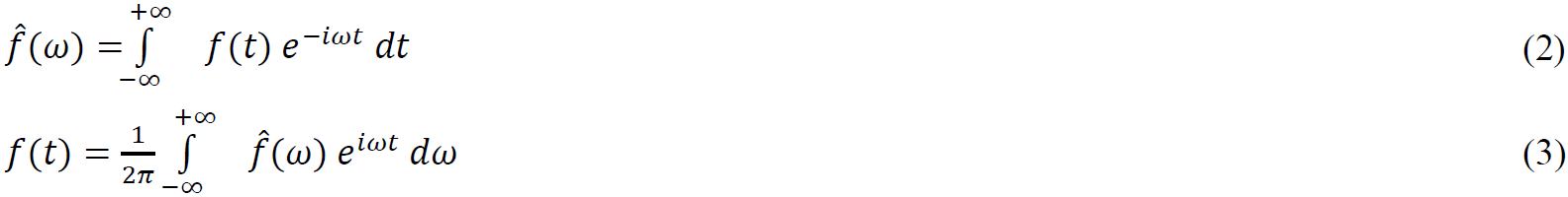
The method of analysing the spectral components (analysis of the direct spectrum and vibration signal envelope spectrum) is the most popular method for generating the domain of informative features, where a team of experts in vibration-based condition monitoring carry out the condition monitoring of industrial equipment. This method, first proposed more than fifty years ago, lies today at the heart of all the most popular vibration-based condition monitoring systems. The basic equations for this method are the Fourier Transform (2) and the Inverse Fourier Transform (3):
Nevertheless, during more than fifty years of active practice, many guides have been written, classifiers (vibration-based condition monitoring maps) have been developed and prescribed for a lot of various equipment types. The analysis of this experience based on many years of applied practice contributes to the development of VibroBox.
VibroBox contains a unit for vibration signal spectrum (power spectral density) and the envelope spectrum analysis, and a number of typical vibration-based condition monitoring maps are used for the retraining of classifiers. On the other hand, all informative features calculated by the vibration signal spectrum and envelope spectrum are involved in forming a vector of informative features of equipment technical condition, which is used by the classifier based on neural networks and fuzzy logic. Also, VibroBox provides trend analysis of the characteristics of the spectrum of the vibration signal and the spectrum of its envelope in order to track the process dynamics.
The graphical interpretation of the development of the belting and bearing (inner ring) defects is shown in Figure 17.
 defects")
6.6. Algorithms for wavelet processing of the vibration signal
Wavelet analysis is a special type of linear signal conversion, well suited for waveform analysis and detecting short-time high-frequency signal fluctuations. The wavelet window provides an adequate estimate of such fluctuations due to an increase in the window amplitude with a decrease in its width. Analysis resolution in time domain increases along with frequency.
These distinctive features of wavelet analysis are very useful for the defects extraction. The emergence and growth of a defect is accompanied by periodic shock pulses of specific shapes. This is a reliable informative feature for a high-quality diagnostics.
Wavelets (short waves) are functions of a specific shape localized along the axis of arguments (independent variables), invariant to shift and linear to the operation of scaling (compression/stretching). They are created via special basis functions, which define their appearance and properties. By localization in the time and frequency representation, the wavelets get an intermediate position between the harmonic (sinusoidal) functions localized in frequency, and the Dirac function localized by time.
A wavelet as a function ψ∈ L2(R) with a zero average:


Most defects in rotary equipment, which include rolling bearings and gears, are accompanied by impact processes with certain resonant frequencies. The vibration signal of the equipment can contain from one to several expressed resonant frequencies, depending on the degree of defect and their number.
It should be noted that from the point of view of the algorithm of wavelet decomposition, the vibration signal is most effectively represented not in the form of a superposition of a large number of signal components, but only with a few that have the largest energy contribution. Working with each of these components separately can improve (simplify) handling both in the spectral domain due to the lack of effect of “overlapping patterns of defects”. In the time domain, due to the fact that each implementation will have one periodic (quasiperiodic) sequence, that simplifies the search for the repetition period of shock pulses.
The basis of the sparse wavelet decomposition is that any signal x(t) can be represented as a superposition of certain basis functions. The sparse representation of such a signal has the form of a set of peaks. Each peak has a corresponding basis function φm with three parameters: amplitude, frequency, and time position. The mathematical expression of this model of a signal with allowance for additive noise is given by the expression:

The amplitude coefficient sim and the time position τim are determined by the method presented in the expression:

 is the remainder after using the basis function φm at time τi;
si is its amplitude.
The accuracy of the signal recovery will depend on the number of iterations of the algorithm execution.
As shown in the algorithm diagram for the sparse wavelet decomposition of the vibration signal (see Figure 18), the first stage of the decomposition of a vibration signal is the calculation of the scalograms, according to which the resonant frequencies in the decomposed signal are determined. A narrow set of basis functions (basis) is formed on selected points, and their rationing (in terms of energy) is performed. On the basis of the signal fragment, the optimal number of iterations of decomposition is calculated. The decomposition is a sequential (iterative) procedure for subtracting the basis functions from the signal until a certain level of decomposition is achieved. Fixing the position, amplitude and scale of the subtracted functions, a sparse representation of the signal is formed (in the form of a set of pulses for each basis function). Based on the decomposition results, the time domain processing (search for periodicity, calculation of the energy contribution, etc.) and frequency domain processing (search for defect patterns) are performed. The final conclusion about the condition of the equipment is made by the decision-making module.

6.7. Basis wavelet function adapted to isolate shock pulse processes
The base of the wavelet transformation is a basis function, the form of which largely determines the effectiveness of the method for solving the specific task. Wavelet bases, in contrast to Fourier transform, have quite a lot of various basic functions whose properties are intended to solve various tasks. The general rule for analysing signals is that the form of the basis function should be as similar as possible to the type of data being analysed.
The signal arising from the impacts of structural elements of industrial equipment has a very specific shape in the time domain: it’s a sharply generated pulse with rapid exponential fade-out. The frequency of faded oscillations is determined by the resonant properties of the structural elements. Therefore, the basis function adapted to detect such impacts must be asymmetric, adapted to isolate the characteristic sharp jump in the amplitude of the oscillations at the beginning of the shock pulse. It also must have a narrow Fourier image, i.e. contain the expressed dominating frequency to be selective in the frequency domain. The law of decreasing function should be exponential, if possible.
The VibroBox uses specially developed sets of basic wavelet functions to detect shock processes in industrial equipment. These functions constitute intellectual property of VibroBox.
An example of the graphical interpretation of implementation of the sparse wavelet decomposition based on the basis wavelet function adapted to isolate shock pulses is shown in Figure 19.
 |
 |

 with isolated shock pulses")
with isolated shock pulses having a resonant frequency Fr = 17 390 Hz (2-nd area on the scalogram).
Figure 19 — An example of implementation of the sparse wavelet decomposition based on the basis wavelet function adapted to isolate shock pulses.
6.8. The vector of informative features of the technical condition of equipment
The vector of informative features of the technical condition of equipment is the most complete description of the vibration signal in terms of identifying possible equipment defects. All the sets of algorithms (methods) used by VibroBox are involved in its formation in order to search for features of the technical condition of equipment.
Thus, in the domain of informative features formed, a classifier is based on neural networks and fuzzy logic transforming sets of features and their dynamics into a condition monitoring report.
6.9. Classification of defects in the domain of informative features
The aim of classifying defects in the domain of informative features is to make the equipment condition monitoring report based on an analysis of the vector of informative features.
The defect classification unit
The classification unit is a preconditioned neural network operating in the domain of informative features of equipment condition.
The task of the classification unit is to decompose the informative features and link them to the relevant equipment states.
The defect validation unit
The validation unit is designed to behaviorally evaluate the “feature-condition” pair in time and reduce the likelihood of a false alarm. The operation principle of the validation unit is based on fuzzy logic technology and allows the service to check whether the classifier's assumptions about the “feature-condition” pair are true.
6.10. Generation of prescriptions for asset technical management
After the system classifies the equipment defect, it is necessary to assign the proper management prescriptions for the equipment. Identifying the defect and stating its existence is not enough. If a problem is identified in time and proper maintenance is performed, you will be able to significantly increase the remaining lifespan of your equipment and its overall reliability.
A special group of Vibrobox algorithms solves this task. The main input data for their processing is the equipment condition monitoring report.
6.11. VibroBox service operating results
Ultimately, VibroBox gives equipment condition monitoring and predictive maintenance reports. These reports are accessible through the user's personal account and can be automatically submitted to enterprise management systems (CMMS, MES, ERP) or any other service by VibroBox API.
6.12. Promising and experimental algorithms
Many important tasks in medicine, science and other industries/services are not fully automated yet. High variability of observational objects, both technical and biological, requires a convenient domain of informative features for a fully automatic classification with minimal risks. Preliminary analysis and formation of detailed description (schemes, templates, threshold levels) is the "classical" approach which inevitably leads to critical errors caused by a limited training data set.
We are working on a universal decision-making system that operates without priori information on the analyzed object. Our algorithms are forming an adaptive domain of informative features that is invariant to objects of observation and does not depend on preliminary training. Our experiments and their results indicate that it is possible to reconstruct a detailed kinematic scheme of equipment from vibration signals. Moreover, the same algorithms can be applied to temporal signals of a different nature (acoustic signals, heart murmur, ECG, EEG etc.).
How do we do this?
Classification of the "raw data" (signals of vibration, speech, heart murmur etc.) without preprocessing is inefficient for many reasons: noise, waveform inconstancy, dependence on environmental conditions, too many dimensions for direct classification etc. Therefore, time, frequency and wavelet domains are used to analyze time signals and present them in a convenient form.
The frequency domain is well studied, has a number of invariant properties, and shows excellent results with stationary signals (which do not change their properties in time). However, it does not contain information on the waveform of the signal, which is very important in many cases. The wavelet domain was introduced to process nonstationary signals. However, it does not analyze the waveform in detail and is focused on energy distribution by time and frequency. Thus, the waveform can be analyzed in detail only in a time domain that does not have a compact and universal (invariant) representation. Sets of simple metrics (RMS, Peak, Crest Factor, Kurtosis etc.) which are calculated using time domain methods by modern systems are not sufficient for reliable classification. That is why the representation of the same time waveform in a compact invariant form allows us to simplify the analysis in areas where the waveform is highly significant (medicine, vibration diagnostics, speech processing, etc.). To greatly improve the performance of neural networks and make them more versatile, our algorithms create a complete description of the signal using all three domains (time, frequency and wavelet).
7. Further development of VibroBox
Today, our scientists are working on algorithms to detect the type of diagnosed equipment and build it's kinematic diagram ("digital twin") from the raw signal (vibration or acoustic), without any additional information. The accumulation of vibration data will help to solve the clustering problem and improve scalability.
We have good results analysing the acoustic and vibration signals from sensors and microphones built into modern smartphones and tablets. Just imagine an express diagnostics by using your phone!.
We are working on integration with top-level platforms, such as General Electric and Microsoft with the platform for Industrial Internet Predix, SAP with SAP Cloud Platform for the Internet of Things and Intel with its Intel IoT Platform and others.
A huge interest in VibroBox is evident on behalf of not only industrial enterprises, but also road freight and railway carriers. We are actively exploring wind energy, rolling stock, automotive and other industries where automated prescriptive maintenance provides obvious economic benefits.
[1] CPS PWG Draft Framework for Cyber-Physical Systems, Release 0.8 / Cyber Physical Systems Public Working Group, 2015.